HPP HIGH PRESSURE PUMPS FOR AN ENTIRE WORLD OF POSSIBLE APPLICATIONS

Hpp is a PTC brand specialized in the design and construction of plunger pumps for water, strengthened by its technological know-how which is backed up by the most modern technology. This means the company is able to offer a wide range of products to meet requirements that go from 16 to 410 kW (from 21 to 550 Hp) with pressures up to 2.800 bar (40k psi).
Hpp pumps are manufactured using the most modern technologies both as regards the materials used and mechanical operations and heat treatments, in combination with a wide range of accessories suitable for the specific needs of the single user. Pumps are mainly intended for municipal services: sludge pumping, washing solid waste containers, street cleaning, etc. but also for a lot of other applications for the industrial sector.
Professionalism and research make it a dynamic modern company intent on tackling and resolving the problems of a fast-evolving market.In terms of innovation, Hpp’s mission is to understand the needs of the market and its customers, in order to stay ahead of the evolutions in demand and supply the best solutions as quickly as possible.
From 2017, Hpp product range is being distributed by PTC Srl, an Italian company based in Rubiera (RE) specialized in the high pressure water jetting technology.
HPP HIGH PRESSURE PUMPS – OPERATION AND COMPOSITION
Efficiency
The HPP plunger pumps fall within the category of the reciprocating positive displacement plunger pumps, i.e., with technical specifications whereby liquid flow occurs by virtue of the variations of one or more capacities which, alternately, suctions and delivers the liquid.
The difference between the maximum and minimum volume of the variable capacity represents the theoretical volume of pumped liquid.
The HPP plunger pumps are of the Triplex type, i.e., they feature three pumping elements, arranged with parallel axes lying on a same horizontal plane.
Mechanical part (Gear-End)
The mechanical part comprises the parts that produce the movement of the pumping elements of the pump. Each pumping element comprises a piston (in turn made up of a “drive piston” and a “pumping piston”, coaxial and integral with each other) to which the reciprocating motion is provided that produces the suction and pressure actions. The reciprocating motion of the piston is produced by a connecting rod-crank system connected to the drive piston by means of a pin and moved by one of the three eccentrics (offset the one to the other by 120°) of a shaft. The shaft is supported by at least two bearings and one of its ends protrudes from the crankcase to get its motion from the motor driving the pump, directly or through a gearbox.
Hydraulic part (Fluid-End)
The hydraulic part of the pump comprises the head, the pumping pistons, the sealing system and the suction/delivery valves.
The pumping piston of the HPP pumps is of the “plunger” type, i.e., the pumped liquid sealing system is fixed, while the piston slides inside. The pumping piston can be made with a bush, in ceramic material, fitted to the drive piston and retained by a screw, or with an integral piston made of very hard material fitted directly on the drive piston. The sealing system acts on the pumping piston to ensure the seal of the pumped liquid during the reciprocating sliding of the pumping piston. The following image shows a possible configuration of the HPP pump.
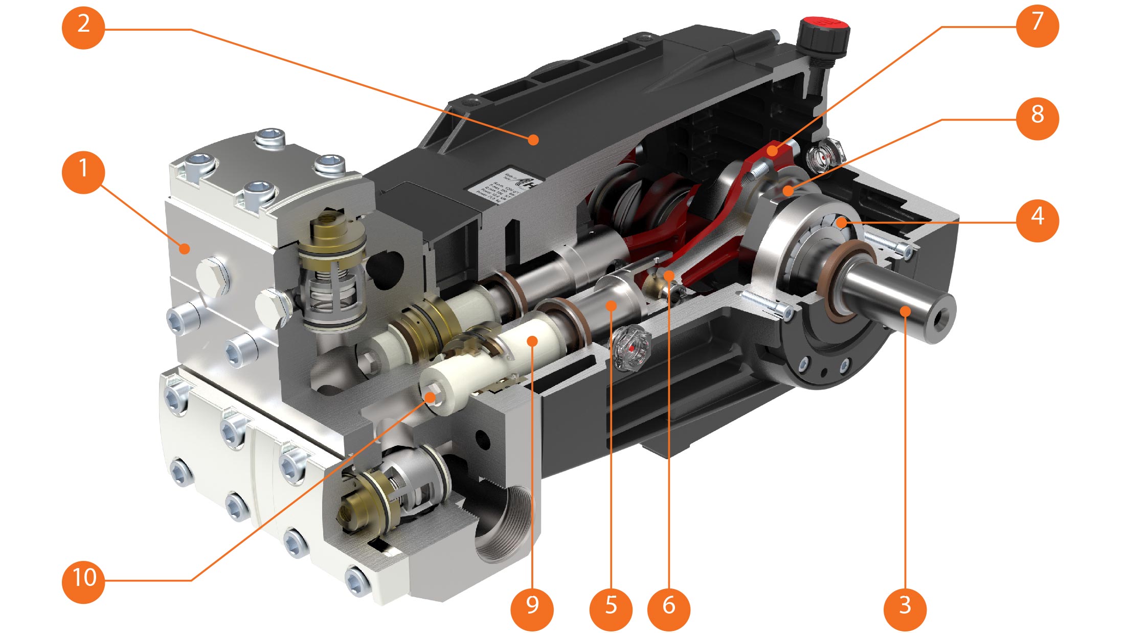 1. Head
2. Crankcase
3. Shaft
4. Bearings
5. Drive piston
6. Pin
7. Connecting rod
8. Eccentric
9. Pumping piston (Bush)
10. Screw
The sealing system on the pumping pistons consists of one or more elements which ensure the seal of the pumped liquid in contact with the piston. The sealing elements can be single gasket, combined gaskets, packing, etc., depending on the efficiency and type of intended pump use. Herein below, the sealing element is generically indicated as a gasket. The sealing system can also be made up of two gaskets set apart: a high-pressure gasket, which ensures the seal of the pumped liquid and a low-pressure gasket which ensures the seal of any liquid that has leaked out of the high-pressure gasket. In this case, an annular chamber is located between the two gaskets. This is normally in communication with the intake manifold. This construction configuration has two functions:
– to create a tank to recover any liquid leaking from the high-pressure gasket and prevent this escaping outside;
– to ensure the presence of liquid between the two sealing elements, including in the absence of any leak from the high-pressure gasket; this keeps the low-pressure gasket wet and prevents it from overheating in the absence of lubrication. In certain cases, the presence of liquid in the annular chamber is ensured by the “flushing” of part of the liquid which flows through the pump. Also generally part of the sealing system are other accessory gasket elements and more specifically pressure rings, gasket support rings and anti-extrusion rings. The presence and construction shape of these accessory elements are linked to various factors among the most important of which are to be deemed the type of gasket adopted and the pump working pressure. The following image shows a possible configuration of the hydraulic part of the pump (Fluid-End), showing the head, a possible sealing system with two separate gaskets and the suction and delivery valves.
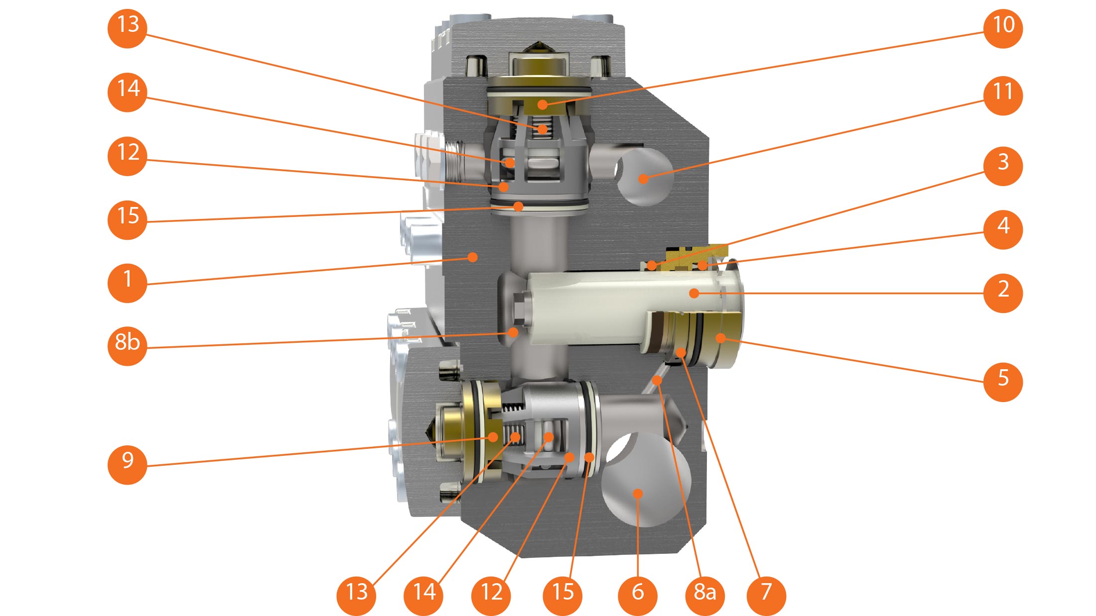 1. Head
2. Pumping piston
3. High-pressure gasket
4. Low-pressure gasket
5. Gasket support rings
6. Intake manifold
7. Annular chamber
8a. Connecting hole to the annular chamber
8b. Pumping chamber
9. Suction valve
10. Delivery valve
11. Delivery manifold
12. Valve cage
13. Valve spring
14. Valve plate
15. Valve seat
Each pumping element of the pump features a suction valve and a delivery valve, positioned in an opposite direction the one to the other. The function of the valves is to intercept the liquid, thereby permitting the pumping action in the working cycle corresponding to the rotation of the shaft. Valve operation is automatic, i.e., opening and closing are determined by the difference in fluid pressure on the valve plate, held in position by the contrasting force of a spring. A complete rotation of the pump shaft determines a suction phase (piston return to bottom dead centre) and a delivery phase (piston moves up to upper dead centre) for each pumping element. During the suction phase, the liquid is suctioned through the suction valve into the pumping chamber obtained in the head, while the delivery valve is closed. In the delivery phase, the liquid is pushed out of the pumping chamber, through the delivery valve, while the suction valve is closed. The pumping elements are connected crossways to each other by means of the suction and delivery manifolds obtained on the head.
THE EFFICIENCY OF THE PLUNGER PUMPS
The efficiency of the Plunger pumps is determined by the following physical quantities:
– Flow rate
– Pressure
– Power
The flow rate is the volume pumped in the unit of time and can be split into a theoretical Flow Rate Qt (the flow rate which can theoretically be supplied by the pump) and an actual flow rate Qe (the flow rate actually supplied by the pump). The Flow Rates are normally expressed by the unit of measurement l/min (metric system) or gpm (system used in English-speaking countries). The Flow Rate Qt is calculated according to the following formula (valid for metric units):

Wherein:
D [mm] = piston diameter
e [mm] = pump shaft eccentricity
n [rpm] = rotation speed
From the above figures in metric units, the flow rate in English speaking country units can be obtained with the formula:

The ratio between the two flow rates, theoretical and actual, defines the volumetric efficiency ηv of the pump:

The flow rate figures shown in the catalogue efficiency are those of the theoretical flow rate Qt, i.e., with volumetric efficiency ηv = 1.
The flow rate of positive-displacement plunger pumps is proportionate to the rotation speed and tends to be independent from the delivery pressure, while tending however to decrease with the increase of the latter. The pressure is the maximum value which can exist in the pump head in operating conditions. It must be pointed out here that positive-displacement plunger pumps do not intrinsically develop pressure during their movement, but move the liquid by virtue of their construction characteristics as described in the previous chapter. If however, downstream of the pump, in the delivery circuit, there is an obstacle (e.g., a nozzle), the pressure needed to enable the pump flow to cross the encountered obstacle is generated in the pump head. The delivery circuit must therefore feature a maximum pressure valve which prevents the occurrence of a pressure above the maximum pressure, set on the basis of the pump resistance characteristics. In fact, if the above obstacle were to form a complete blockage (e.g., total closing of the delivery circuit), the pressure would increase exponentially with consequent breakage of the head. If an adjustable by-pass valve is fitted, furthermore, a determinate pressure value can be set according to operating needs. Pressure is indicated in metric units, in bar, in MPa and in English-speaking country units in PSI. The relations between the above units of measurement are the following:

The effective power Nu of a pump is the energy provided to the pumped liquid in the unit of time, while the absorbed power Na is the energy in the unit of time which the pump requires from its energy source (electric, thermal, hydraulic motor, etc.) to perform the required pumping operation. The units of measurement used to express the Power are kW, CV and HP.
The effective power Nu is calculated with the formula:

The ratios between the other power units of measurement are as follows:

The absorbed power is tied to effective power with the ratio:

wherein ηt is the total efficiency of the pump produced by the three efficiencies ηv (volumetric), ηm (mechanical) and ηi (hydraulic). The volumetric efficiency ηv normally takes on values between 0.85 to 0.95. Lower values occur in pumps with higher pressures and higher rotation speeds, while higher values occur in pumps with lower pressures and lower rotation speeds.
Hydraulic efficiency ηi expresses the losses for resistances opposing the flow through the head and for high pressures typical of plunger pumps, and has values close to the unit. Mechanical efficiency ηm expresses the power drops in the mechanical-kinematic part: values are normally around 0.94÷0.96. On the basis of the above, the total efficiency ηt therefore takes on the lowest values (0.78÷0.80) in plunger pumps with higher pressures and higher rotation speeds and the highest values (0.90÷0.92) in plunger pumps with lower pressures and lower rotation speeds. The power values shown in the catalogue efficiencies are those of the absorbed power Na. The absorbed power in positive-displacement plunger pumps, with constant rotation speed (and therefore with constant flow rate) is proportionate to pressure.
CONTACT US
HPP APP AND CERTIFICATIONS